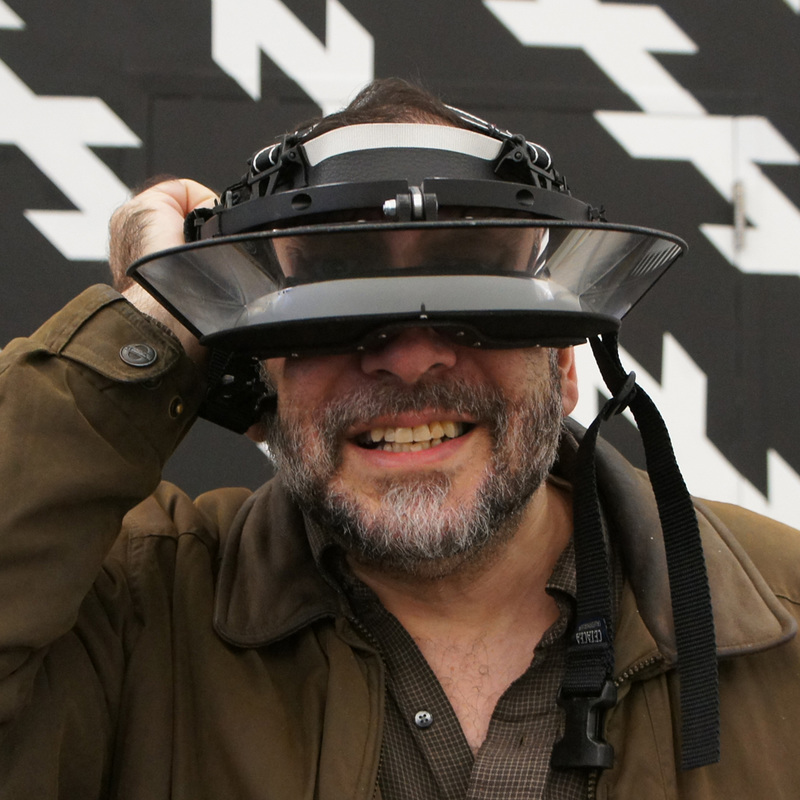
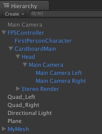
More recently there are devices that capture stereoscopic photos and videos for iPhone, Androids, and GoPros. They have nice viewers to display images in 3D. But what if you want to go further and maybe turn them into a 3D gallery, or perhaps add some interactivity? It would behoove you to place and render these assets in a VR setting with programmatic interactivity, such as Google Cardboard, Gear VR, or Oculus. It turns out there are some challenges if you want to place stereoscopic images within a traditional vr scene. This is because you have to render the photographic images differently for the left and right eye. This article gives you the basics on how to accomplish this in Unity for both Google Cardboard and Gear VR/Oculus. Before launching into the nitty gritty I want to say a few things. The techniques described are almost identical for Google Cardboard and Gear VR/Oculus. They are different enough that they'll be discussed separately. Placing 3D video in a VR scene works, but it is vastly more complex, as it is highly dependent upon deployment platform, file formats, and the like. So 3D video is not going to be discussed in this article (perhaps, it'll appear in a future article). The basic assumption here is that you already have familiarity developing VR Apps with Unity using their built-in VR support for Gear VR/Oculus or an external package for Google Cardboard. An additional assumption is that you are on Unity 5.2 or later. The steps provided here apply equally well whether you are developing on a Mac or PC or are using the Pro or Personal Edition of Unity. Basic strategyStereoscopic images have a left and right part, corresponding to what the left and right eyes each sees. In the Unity natively supported VR there is only a need for one Camera. By enabling VR support in the Player settings, Unity automatically generates two sets of Game Views slightly offset from one another based on the position and orientation of the main camera. This works fine for a generic game view, but it immediately throws a monkey wrench into the gears when you want to place in your scene two sets of images, one for each eye. So basically, you have to tell Unity to construct the view for each eye a bit differently. Fortunately, for images, there's really no scripting involved. Putting Stereoscopic images in Google CardboardStart out with a stereoscopic image like the following:  You will need split the image into two parts; one that will be visible only to the left eye, and the other only visible to the right eye. This is easily done with a photo-editing program like PhotoShop. Just cleave the image into two separate halves. You can save it as a PNG or JPG file. For purposes of this article, we'll be using the files called Left_Eye_Image.png and Right_Eye_Image.png. You will be importing these into your VR scene in Unity. If you don't already have an existing Unity Cardboard project, you can start from scratch. Just be sure to do the necessary generic steps for creating Unity Cardboard Apps. For example if you are developing for Android you'd setup the Android SDK, within Unity switch build platform to Android, import the Unity for Cardboard Integration package, adjust your Player/Build settings, and do the necessary setup of Developer Options on your Android phone. Chances are if you successfully built any Google Cardboard App with Unity, you've done all these steps. The only thing you would need to do, is make sure you have the right build settings for this Unity Project. So start out with any Hello World Unity project that's Cardboard enabled. If you have a generic main camera, disable or delete it, as Cardboard will be doing the camera work. From the Unity Standard Assets, import into your project a FPSController asset. This will include a FPSController Prefab. Drag the prefab to your Hierarchy. You can position the FPSController anywhere you want. In the example used for this article the x-y-z position is (9,25, 2). You will notice that the FPSController has a child called FirstPersonCharacter. If there is a checkmark for Camera. Uncheck it to disable this camera. In your Cardboard folder for your Project there's a Prefabs folder that contains a CardboardMain prefab. Drag this prefab directly onto the FPSController in your Hierarchy so that both FirstPersonCharacter and CardboardMain are direct children of the FPSController. So the overall Hierarchy organization should look something like the following:
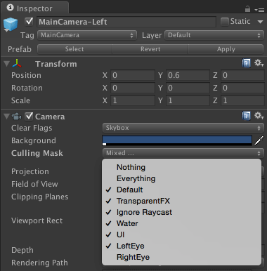
There are items shown in this hierarchy which we'll be introducing shortly (such as the Quads). For the moment do not concern yourself with MyMesh component. This was something that's created for other assets in the scene as well as some scripts to manage interaction. In the Assets folder of your project create a Resources folder. Import the two files- Left_Eye_Image.png and Right_Eye_Image.png and place them inside the Resources folder. At this point make sure you have saved the current scene. It can be any name of your choosing. When it comes time to build your App be sure to set your build settings to this scene. In your project Hierarchy add a flat surface having a mesh renderer and a shader into your scene. You might use a plane or a quad. In our example, we'll use Quads. Give this quad the name Quad_Left. Drag the Left_Eye_Image asset from your Resources folder on top of the Quad_Left item in your Hierarchy. Now your Quad_Left item will use the Left_Eye_Image.png file as its shader. Size and position your Quad_Left so that it's readily visible in your Game View and has the proportions you desire. In this example the PNG file is 854x1486 pixels. The quad we are using has the scale of 54.24 for x, 94.38 for y, and 1 for z; so it keeps the same aspect ratio as the PNG file. In the example shown, the x-y-z position of the Quad_Left is (8, 8, 60). Everything you did for the Quad_Left needs to be done equivalently for Quad_Right. Basically, it's easy to copy and paste the Quad_Left and rename the pasted item to Quad_Right Of course, be sure to replace the Left_Eye_Image.png with Right_Eye_Image.png. Both the Left_Quad and Right_Quad are directly on top of one another. Our next task is to tell the left and right cameras inside CardboardMain to exclude the quad that doesn't correspond to the matching eye. Here are the basic steps: . Edit your Tags and Layers. 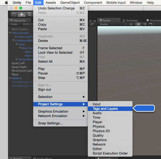 Add two new layers, one of which will only be visible to the left camera and one that will only be visible to the right camera. So create the layers here. The filtering gets done downstream. 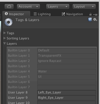 Now we're going to tag the Quad_Left and Quad_Right objects accordingly. Select your Quad_Left in the Hierarchy. In the Inspector panel change the Layer tag from Default to Left_Eye_Layer.. 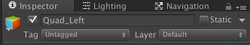 Change the layer from Default to Left_Eye_Layer. 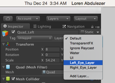 The resulting setting for Quad_Left should look like the following: 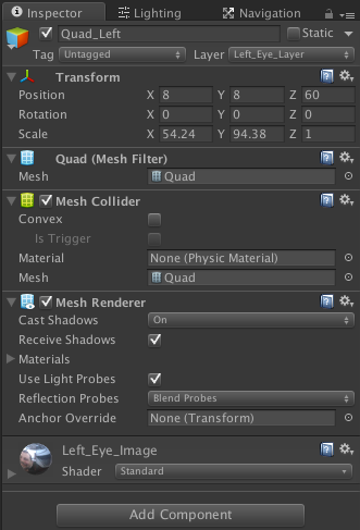 For the Quad_Right it's essentially the same except that its set to Right_Eye_Layer. You might think that at this point we're done; but not quite yet. You have to tell the cameras for the left and right eyes to exclude the quad tagged to the other eye. I guess you could call this "Turning a blind eye"? In your Hierarchy select the MainCameraLeft. In the Inspector panel adjust the MainCameraLeft properties. Note that Camera (under Transform) should be unchecked and that the CardboardEye script is checked. Make sure that Eye is set to Left. Now make sure the Toggle Culling Mask (for your MainCameraLeft) is set to Right_Eye_Layer. This basically tells the left eye camera to ignore the quad that gets rendered for the right eye. 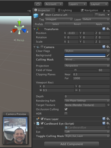 Now of course, do the equivalent for the MainCameraRight. At this point you should be able to test this out in the Unity Editor (press Cmd-P for Mac or Ctrl-P for Windows). 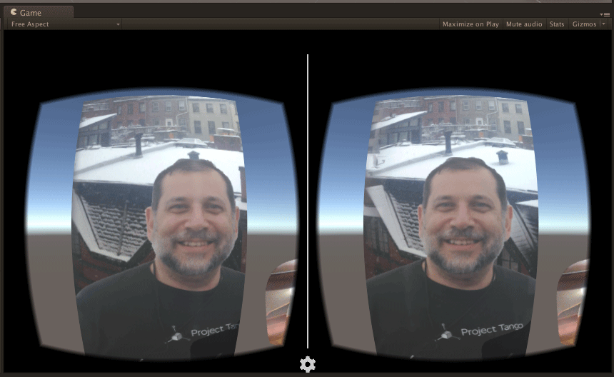 For your build settings be sure to switch to your deployment platform (Android or IOS) and make the appropriate settings, including remembering to specify the project scene. Since this is a Cardboard App (as of Unity 5.2,/5.3) you would not enable Virtual Reality Supported. This is because Cardboard does all the heavy lifting. When you get to Gear VR or Oculus it's a different story. Unity natively supports Gear and Oculus, so the Virtual Reality Supported setting would checked to enable VR. Putting Stereoscopic images in Gear VR and OculusThe setup for Gear VR or Oculus is very similar to what we did with Cardboard. So this will be an abbreviated description. I want to outline a few distinctions between the Gear VR/Oculus setup vs. Cardboard.
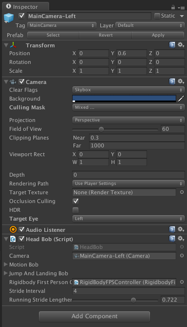 Your Hierarchy would look something like the following: 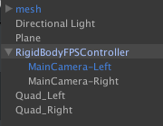 You don't need to concern yourself with the item called mesh. It has some stuff that I threw in for other assets and interactions. As you created a MainCamera-Left, do the equivalent for MainCamera-Right. A few points are worth mentioning:
So there you have it. Now you can mix stereoscopic images in your VR scenes!
At some point I will update this article; I suspect that the Google Cardboard one day will be natively supported inside Unity. Also, I would like to cover rendering 3D Video inside VR. This topic is too messy and complex to give you something you can easily use.
This hackathon was only 2 days, so I had to simplify what I wanted to make in that time. I figured only one orientation sensor should be enough to get a good pointing device working. The orientation sensor that I chose to use was the BNO055 from Adafruit. Check out the information for it here:
http://www.adafruit.com/product/2472 The best part about the BNO055 is that you can get the quaternion data out of it directly. Getting the quaternion data is incredibly useful since all rotations in Unity3D are done with quaternions. The BNO055 was connected to an Arduino Due. It uses the i2c interface and the Wire library to work. So the SDA and SCL pins from the BNO055 were connected to the Arduino D20(SDA) and D21(SCL) pins respectively. The other pins on the BNO055 besides 5V and ground weren't used due to the speed in which I was trying to get this project done. An Arduino Uno was added which had an MP3 Shield from Sparkfun connected to it. The serial1 connection of the Due was connected to the serial connections of the Uno. You can find it and more information about it here: https://www.sparkfun.com/products/12660 On the 2gb microSD card of the MP3 player Shield I uploaded a bunch of random light saber noises that I found online. I wasn't really concerned with what the noises were at this point, just that I had a variety of them to work with. The second Arduino was used because the MP3 Shield also uses the SPI interface to run the MP3 Shield, and the pinout is totally different for the SPI pins on the Due. I didn't have time to get it all integrated so it was just easier to add another Arduino. The output from the MP3 player shield was piped into an Adafruit 20W stereo amplifier. This is a super powerful amp for its size, you can find out all about it here: https://learn.adafruit.com/adafruit-20w-stereo-audio-amplifier-class-d-max9744 The stereo amp was running two surface transducers. Surface transducers are basically speakers with the speaker cone removed, and a good mounting point put in its place. The surface transducers I choose for this were the Sparkfun small surface transducers. They are really loud for their size if you have them mounted solidly to a surface. These transducers are very fragile though. The best thing to do with them is to solder your speaker wire onto the connections and then cover that connection in hot glue. If you plan on handling them after they are connected your going to have the terminals rip out and it'll never work again. You can find the surface transducers here: https://www.sparkfun.com/products/10917 This whole thing had to communicated to either a computer or smartphone wirelessly. The natural choice for that would be to use Bluetooth. Sparkfun makes an incredibly easy to use Bluetooth module called the BlueSMiRF. I went with the BlueSMiRF Gold module for this application, though the Silver edition would work just as well. You can find information on getting the BlueSMiRF bluetooth module setup here: https://www.sparkfun.com/products/12582 All of this stuff wired together was powered by a Turnigy 3 cell LiPo pack that I pulled out of my quadcopter. Its giant and had much more power then I'd ever need for this project. At full charge a 3 cell Lipo pack gives out 4.2volts per cell which gives me 12.6 volts output. This was perfect to run the 20W amplifier, since this LiPo pack has a high C rating and will not be over burdened by sudden current draw from the amplifier. The Arduino Uno and Arduino Due were also connected to the LiPo and ran perfectly due to the internal voltage regulator on the Arduinos. The nicest part of using this LiPo pack was to connect to the Arduino through the balance charging port on the battery. When connecting through the balance charging port you can just plug standard jumper wires into the port, without having to do some hackery with alligator clips on the main output of the battery. You can get the LiPo pack here: http://www.amazon.com/Turnigy-2200mAh-20C-Lipo-Pack/dp/B0072AEY5I/ref=sr_1_1?ie=UTF8&qid=1443729735&sr=8-1&keywords=3+cell+lipo Here is a quick breakdown of how all of this stuff is connected. The Arduino Due is getting orientation data from the BNO055 through the I2C interface. It is also handling bluetooth communication with the BlueSMiRF. The Due is controlling the Arduino Uno with the MP3 Shield on it. The MP3 Shield is outputting sounds into the 20W amplifier and that amplifier is connected to two small surface transducers. The Arduino Uno is running the FilePlay example from here: https://github.com/madsci1016/Sparkfun-MP3-Player-Shield-Arduino-Library/tree/master/SFEMP3Shield Lets see how this all ties together on the Arduino Due code.
     If we connect to the BlueSMiRF over your serial this is what you'll be greeted with when you start it up.
Ready for action!
Orientation Sensor Test ------------------------------------ Sensor: BNO055 Driver Ver: 1 Unique ID: 55 Max Value: 0.00 xxx Min Value: 0.00 xxx Resolution: 0.01 xxx ------------------------------------</code> ? - Prints this help menu. dataPush - dataPush 1, dataPush 0, determines whether to push data or not mp3rand - mp3rand, plays a random MP3 qWXYZcsv, 0.993957, 0.098633, 0.048218, 0.000061,xyzOrientation, 359.94, -11.25, -5.56, eulerXYZ, 359.94, -11.25, -5.56, qWXYZcsv, 0.993957, 0.098633, 0.048218, 0.000061,xyzOrientation, 359.94, -11.25, -5.56, eulerXYZ, 359.94, -11.25, -5.56, qWXYZcsv, 0.993957, 0.098633, 0.048218, 0.000061,xyzOrientation, 359.94, -11.25, -5.56, eulerXYZ, 359.94, -11.25, -5.56, qWXYZcsv, 0.993957, 0.098633, 0.048218, 0.000061,xyzOrientation, 359.94, -11.25, -5.56, eulerXYZ, 359.94, -11.25, -5.56, qWXYZcsv, 0.993957, 0.098633, 0.048218, 0.000061,xyzOrientation, 359.94, -11.25, -5.56, eulerXYZ, 359.94, -11.25, -5.56,
First it checks that the BNO055 is working and outputs some mostly unnecessary sensor information. Then it prints out the help menu. When the help menu is up I sent in the command "dataPush 1" followed by a carriage return. This then set pushData to 1 and caused it to start reading and outputting the orientation data from the BNO055. The orientation data first is the quaternion data in format WXYZ, then we have it in XYZ, then as its Euler angles. XYZ and Euler are equivalent.
Nows the tricky part. Getting Unity3D to get that orientation data and do something useful with it. Startup Unity and make a new empty project. Make a cylinder game object and place it anywhere within the scene. Then go into build settings > player settings> other settings> optimization>api compatibility level, and set that to ".Net 2.0" . We need it set to .Net 2.0 not subset so that we have full access to the serial ports on the computer. I made a new script called bnoRotator.cs and attached that to the cylinder. Here it is:
|
ArchivesCategories |
||||||||||||||||||||||||||||||||||||||||||||||||||||||||||||||||||||||||||||||||||||||||||||||||||||||||||||||||||||||||||||||||||||||||||||||||||||||||||||||||||||||||||||||||||||||||||||||||||||||||||||||||||||||||||||||||||||||||||||||||||||||||||||||||||||||||||||||||||||||||||||||||||||||||||||||||||||||||||||||||||||||||||||||||||||||||||||||||||||||||||||||||||||||||||||||||||||||||||||||||||||||||||||||||||||||||||||||||||||||||||||||||||||||||||||||||||||||||||||||||||||||||||||||||||||||||||||||||||||||||||||||||||||||||||||||||||||||||||||||||||||
 RSS Feed